FE35FB-01000 User Manual
This manual is suitable for the laser scanning sensor FE35FB-01000.
Author: Hinson Release Version: V1.00 Update Time: 2024.10.16
1.1 Notes on Applicable Environment
 Steam, smoke, dust, and visible particles in the air may cause the sensor to misjudge or even become unusable.
 Qualified technicians should regularly check whether the sensor's connections and installations are correct.
 The maximum service life of the sensor is 10 years; after that, it must be replaced, otherwise it may not meet the required performance standards.
 The sensor should be checked and cleaned regularly.
 This product is only allowed to be used within the specified limits and under designated technical parameters and operating conditions at all times.
1.2 Notes on Wiring Environment
 Do not reverse the power supply or connect it to a voltage higher than the specified maximum operating voltage, as this may damage the sensor.
 Connecting the power supply below the specified minimum operating voltage will cause the sensor to malfunction or operate abnormally.
 Please follow the manual instructions for wiring; otherwise, the sensor may not correctly detect the input signal.
 Do not exceed the sensor's load capacity when connecting devices to the output signal terminal, as this may cause sensor failure.
1.3 Notes on Debugging Environment
 Only qualified authorized personnel are allowed to connect, install, debug, and set the laser sensor.
 Ensure that the peripheral devices associated with the sensor are in a reliably stopped state.
 Ensure that the debugging personnel are in a safe position.
 Ensure that other personnel or objects are outside the active range of the equipment.
| Performance | |
Detection Distance |
0.05m-8m (@ reflectivity 2%) 0.05m-35m (@ reflectivity 90%) |
Detection Angle |
312° |
Measurement Frequency |
540Khz |
Measurement Method |
Pulse ranging technology (PRT) |
Scanning Frequency |
12.5Hz: 750r/min (0.025°, 0.05°, 0.1°, 0.25°, 0.5° angle resolution) 25.0Hz: 1500r/min (0.05°, 0.1°, 0.25°, 0.5° angle resolution) |
Object Shape Recognition |
Any shape, resolution calculated based on sensing distance |
Measurement Resolution |
1mm |
Absolute Accuracy |
±10mm |
Measurement Noise |
±20mm |
| Interface | |
Switching Input |
4*NPN |
Switching Output |
4*NPN |
CAN |
Can bus CAN OPEN *1 |
Ethernet |
TCP/IP (TCP server, UDP) 100M |
Number of Echoes |
3 |
Output Raw Measurement Data |
Supported |
Number of Area Protection |
3 |
Number of Obstacle Avoidance Channels |
64 |
| Mechanical/Electrical | |
Operating Voltage |
DC10~30V |
Operating Current |
125-150mA |
Power Consumption |
< 3.4W |
Light Source Wavelength |
905nm |
Laser Class |
Class 1 (IEC 60825-1:2014) |
Indicator Light |
4*LED (Working status display light green, output status display light yellow, orange, red) |
Material |
Aluminum alloy, PMMA |
Protection Level |
IP65 |
1 |
FE Laser Sensor |
1 unit |
2 |
Hinson Configuration Software |
1 set |
3 |
Sensor Qualification Certificate |
1 piece |
Software Tools |
Software version Hinson 1.5.2 or above |
1 set |
Power Supply |
DC24V Power Supply |
1 piece |
Tools |
The computer configuration has an RJ45 port (or obtained through conversion) |
1 piece |
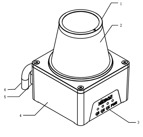
Serial Number |
Function Description | Remarks |
1 |
Top Cover | Indicate scanning range and angle position |
2 |
Sensor detection window | Sensor detection window |
3 |
Indicator Light | Display working status |
4 |
Base | Installation hole position |
5 |
Output Line 1 | Ethernet cable connection |
6 |
Output Line 2 | Power and IO signal line connection |
4.3 Indicator Light Description

Identification |
Display |
Function Description | Operating Instructions |
PWR |
Green |
Working status indicator light | Green indicator light Off: Sensor is not powered or not working properly; On: Sensor is working normally; Flashing: Sensor detects internal fault, stops working; |
Q1 |
Yellow |
OUT1 Output Indicator Light | Yellow indicator light Off: Sensor is not powered, no object detected; On: Intruding object detected; Flashing: Sensor detects trigger edge; |
Q2 |
Orange |
OUT2 Output Indicator Light | Orange indicator light Off: Sensor is not powered, no object detected; On: Intruding object detected; Flashing: Sensor detects trigger edge; |
Q3 |
Red |
OUT3 Output Indicator Light | Red indicator light Off: Sensor is not powered, no object detected; On: Intruding object detected; Flashing: Sensor detects trigger edge; |
|
|
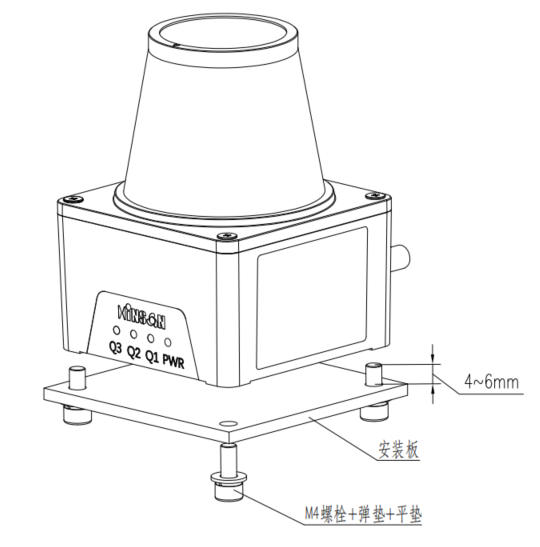
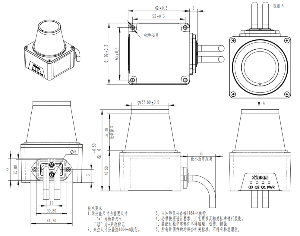
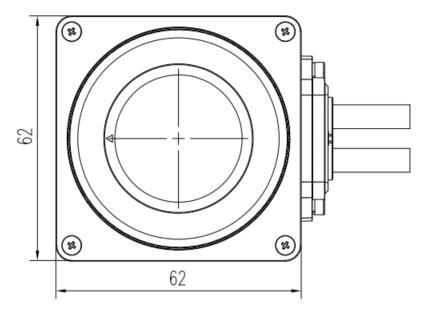
Fixed screws must have spring washers to prevent loosening |
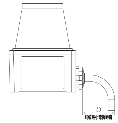
Reserve 30mm space at the rear for cables |
5.1 Power and Switch Quantity Ports
| Function | IO, Power Supply, Ethernet Communication |
| Type | Wires |
| Terminal Specifications | RJ45, FT10001-F2H |
| Number of Pins | 14 pins |
| Output Method | Direct output |
Terminal |
Serial Number |
Symbol |
Color |
Function |
CN3 |
Pin1 |
+VIN |
Brown |
Power positive input |
Pin2 |
-VIN |
Blue |
Power negative input | |
Pin3 |
XCOM |
Brown-white |
Input common terminal | |
Pin4 |
IN1 |
Black |
IO input 1 | |
Pin5 |
IN2 |
Orange |
IO input 2 | |
Pin6 |
IN3 |
Yellow |
IO input 3 | |
Pin7 |
CAN_L |
Green |
CAN_L | |
Pin8 |
CAN_H |
Purple |
CAN_H | |
Pin9 |
IN4 |
Gray |
IO input 4 | |
Pin10 |
YCOM |
White |
Output common terminal | |
Pin11 |
OUT1 |
White-green |
IO output 1 | |
Pin12 |
OUT2 |
White-blue |
IO Output 2 | |
Pin 13 |
OUT 3 |
Red |
IO Output 3 | |
Pin 14 |
OUT 4 |
White and Red |
IO Output 4 |
Terminal |
Serial Number |
Symbol |
Color |
Function |
CN2 |
Pin1 |
ETH TX+ |
Red and White |
Ethernet Output + |
Pin2 |
ETH TX- |
Red |
Ethernet Output - | |
Pin3 |
ETH RX+ |
Green and White |
Ethernet Input + | |
Pin4 |
ETH RX- |
Green |
Ethernet Input - |
5.2.1 Input Signal Connection
The input is an NPN signal, using opto-isolated input.
Use external power supply: XC0M input DC24V±20%, above 100mA;
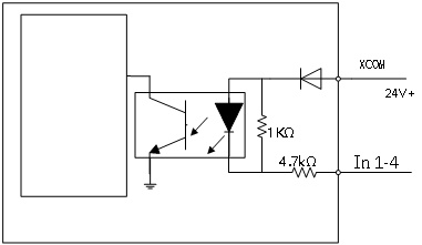
The sensor has 16 channels, which input signals are combined through 4 IO ports to switch to the specified channel number. The detection range of the channel needs to be set in advance through configuration software. External devices select and switch regions through input signals.
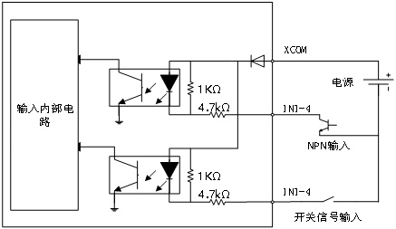
FE sensor provides 4 input ports to combine signals.
ON: Signal is present;
OFF: No signal or open circuit;
| Channel Number | IN4 | IN3 | IN2 | IN1 |
| 63 | OFF | OFF | OFF | OFF |
| 62 | OFF | OFF | OFF | ON |
| 61 | OFF | OFF | ON | OFF |
| 60 | OFF | OFF | ON | ON |
| 59 | OFF | ON | OFF | OFF |
| 58 | OFF | ON | OFF | ON |
| 57 | OFF | ON | ON | OFF |
| 56 | OFF | ON | ON | ON |
| 55 | ON | OFF | OFF | OFF |
| 54 | ON | OFF | OFF | ON |
| 53 | ON | OFF | ON | OFF |
| 52 | ON | OFF | ON | ON |
| 51 | ON | ON | OFF | OFF |
| 50 | ON | ON | OFF | ON |
| 49 | ON | ON | ON | OFF |
| 48 | ON | ON | ON | ON |
Reminder: If not all 16 channels are needed, the input signals can be determined based on the required number of channels.
Switching Time
After the sensor receives the channel switching signal, there is a switching delay due to the scanning cycle. The switching delay is shown in the figure below.
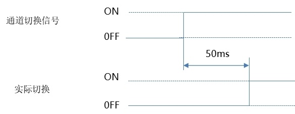
NoteWhen switching to a channel without a graphic, the sensor will continue to monitor the state of the previous graphic channel;
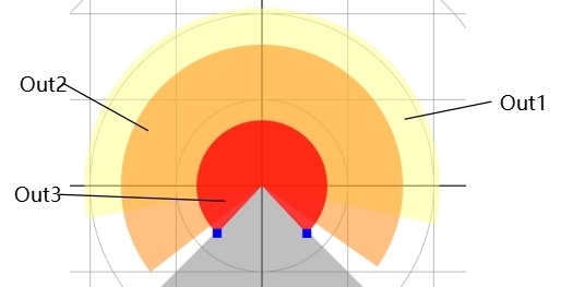
Output signal uses function
| Port | Function | Output Logic |
| OUT1 | Used for remote obstacle warning and deceleration; | Default: Normally closed, can be changed to normally open through configuration software; |
| OUT2 | Used for normal obstacle detection and stopping; | Default: Normally closed, can be changed to normally open through configuration software; |
| OUT 3 | Used for near-end emergency stop; | Default: Normally closed, can be changed to normally open through configuration software; |
| ERR | Used for sensor fault status output; | Default: Normally open, cannot be changed; |
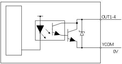
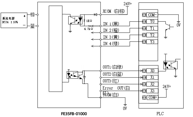
Output is a collector open (NPN) signal, using opto-isolated output, the output voltage is 0V- when there is a signal.
All output ports are NPN outputs. Please refer to the schematic diagram below:
|
||
The sensor output ports correspond to the graphics drawn in the configuration software.
|
||
| Note:Detection output will only occur when the corresponding output has a drawn graphic; | ||
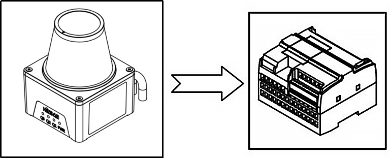
5.2.4 Connection Diagram
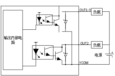
Wiring when all 16 channels and all outputs are fully utilized.
|
|
| FE35FB--01000 PLC | |
| The figure shows the upper computer outputting signals through NPN tubes and receiving signals. | |
X0-X3 are the signal input ports of the PLC; |
|
| Note:Input and output ports must not be short-circuited or connected to loads exceeding the specified current, otherwise it may cause damage to the sensor. |
| DC Power Supply | Voltage | DC10V-DC30V |
| Current | Above 1A | |
| Computer | System | Windows 7 and above |
| Port | Equipped with RJ45 interface or equipped with USB to RJ45 network cable interface | |
| Resolution | Above 1280*720 |
6.2 Connection between sensor and configuration software

6.2.1 Open configuration software
Unzip the configuration software and double-click After entering the 'Device List' interface, click
 Enter the following interface:
Connect the sensor and configuration software according to the following steps 1, 2, 3, 4.
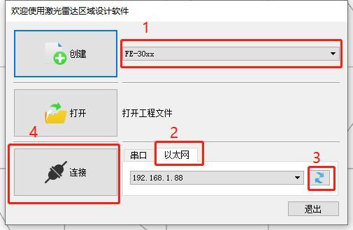
After the sensor is connected to the configuration software, the following interface is displayed:
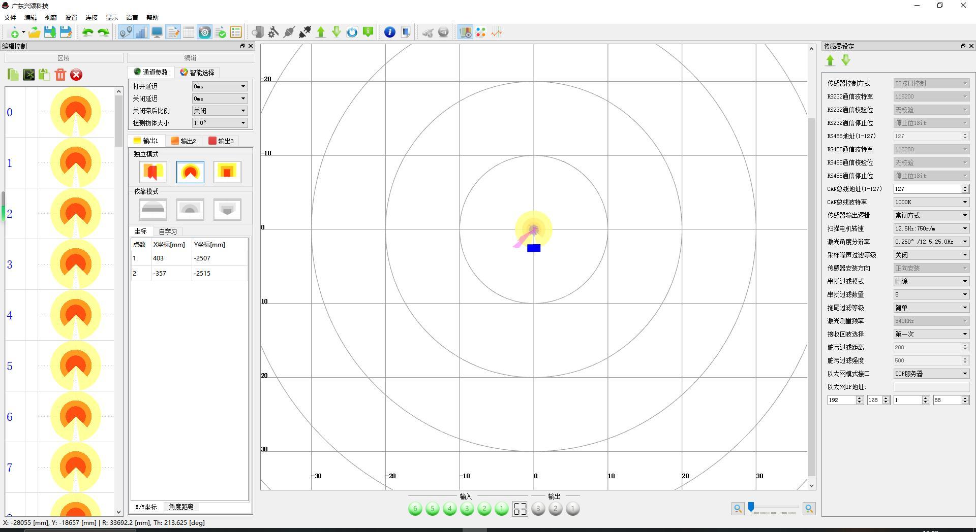
Primary Menu |
Secondary Menu |
Tertiary Menu |
Corresponding Icon | Remarks |
|---|---|---|---|---|
File |
New File |
- |

|
New File |
Open File |
- |

|
Open an existing file | |
Save File |
- |

|
Save the edited file | |
Save As |
- |

|
Save the edited file as | |
Exit |
- |

|
Exit the current configuration software interface | |
Edit |
Undo |
- |

|
Undo the last operation |
Redo |
- |

|
Restore the last operation | |
Copy |
- |

|
Copy the detection graph of a certain detection channel | |
Cut |
- |

|
Cut the detection graph of a certain detection channel | |
Paste |
- |

|
Paste the detection graph of a certain detection channel to another channel | |
Delete |
- |

|
Delete the currently selected detection channel graph | |
Delete All |
- |

|
Delete all detection channel graphs | |
Apply Settings |
- |

|
- | |
Window |
Window |
Edit |

|
Click the icon to display the editing function box of the configuration software |
Monitoring |

|
Click the icon to display the monitoring status of the configuration software | ||
Sensor Settings |

|
Click the icon to display the sensor parameter setting function box of the configuration software | ||
Input and Output Simulation |

|
Click the icon to display the sensor input and output simulation function box | ||
Self-check Status |

|
Click the icon to display the sensor self-check status | ||
Distance |
- |

|
Click to close or display the current 320° range scanning profile of the sensor | |
Intensity |
- |

|
Click to close or display the reflection intensity of obstacles | |
Data List |
- |

|
The configuration software does not support the distance data output of all current detection points, this item is not available | |
Settings |
Serial Port |
- |

|
The sensor does not support serial port connection to the configuration software, this item is not available |
Ethernet |
- |

|
Click to select Ethernet connection to the configuration software |
|
Serial Port Settings |
- |

|
The sensor does not support serial port connection to the configuration software, this item is not available |
|
Ethernet Settings |
- |

|
Click to view the current Ethernet address of the sensor |
|
|
Interface |
Serial Port |

|
The sensor does not support serial port connection to the configuration software, this item is not available |
|
Ethernet |
|
||
Connect |
Connect Device |
- |

|
Click to connect the sensor to the configuration software |
Disconnect Device |
- |

|
Click to disconnect the sensor from the configuration software |
|
Upload Data |
- |

|
Click to upload the detection channel graph and various parameters set for the sensor |
|
Download Data |
- |

|
Click to download the detection channel graph and various parameters |
|
Restart Device |
- |

|
After setting the detection channel graph and its parameters, click this icon to restart the sensor for the parameters to take effect |
|
Sensor Information |
- |

|
- | |
Display |
Graph Display |
- |

|
Click this icon to display the sensor's 320° scanning profile as a planar graph |
Point Cloud Display |
- |

|
Click this icon to display the sensor's 320° scanning profile as a point cloud |
|
Line Display |
- |

|
Click this icon to display the sensor's 320° scanning profile as lines |
|
Language |
Simplified Chinese |
- |

|
Click this icon to display the configuration software in Chinese |
English |
- |

|
Click this icon to display the configuration software in English |
|
Help |
About |
- |

|
Click this icon to display version information of the configuration software |
Guide |
- |

|
6.2.3 Shortcut Icons
All shortcut icons are explained in Section 1 of the menu bar.
6.2.4 Detection Channel Graphic Editing
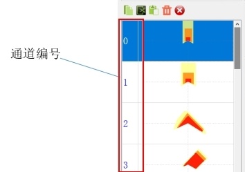
The sensor supports detection channels 0-63, each detection channel supports 3 detection area graphic outputs. The sensor can select channels via Ethernet and output whether there are obstacles invading the 3 detection areas of the channel.
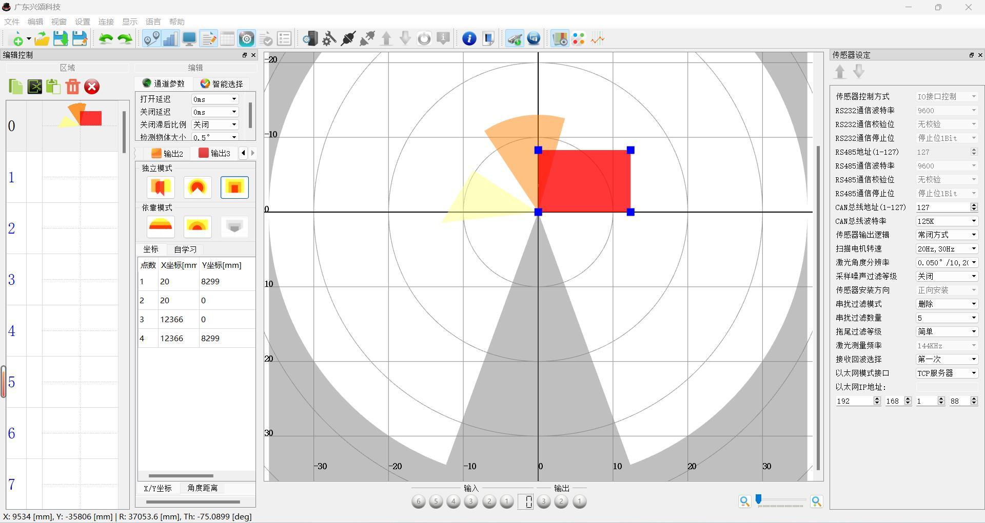
6.2.5 Output Editing
Channel detection graphic output 1, output 2, output 3 editing mode.
Independent Mode: In independent mode, irregular shapes, sectors, and rectangles can be set separately, where irregular shapes can consist of up to 100 connected points.
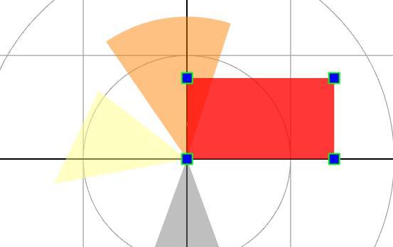
Dependent Mode: After setting the graphic of output 1, you can choose dependent mode to copy the graphic of output 1 at different scales.
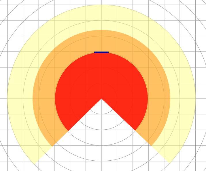
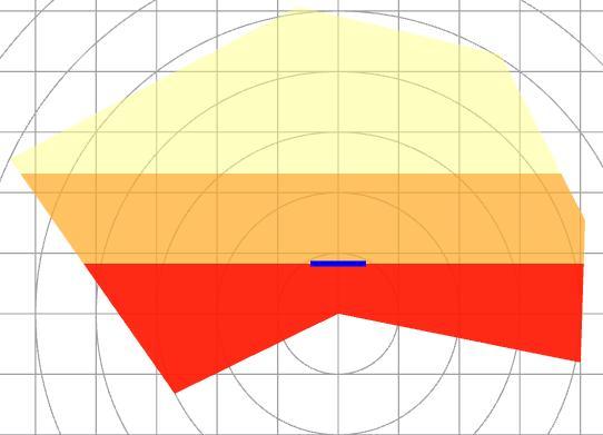
6.2.6 Coordinates and Angle Values
Coordinates (X, Y) of each point of the irregular shape in independent mode:
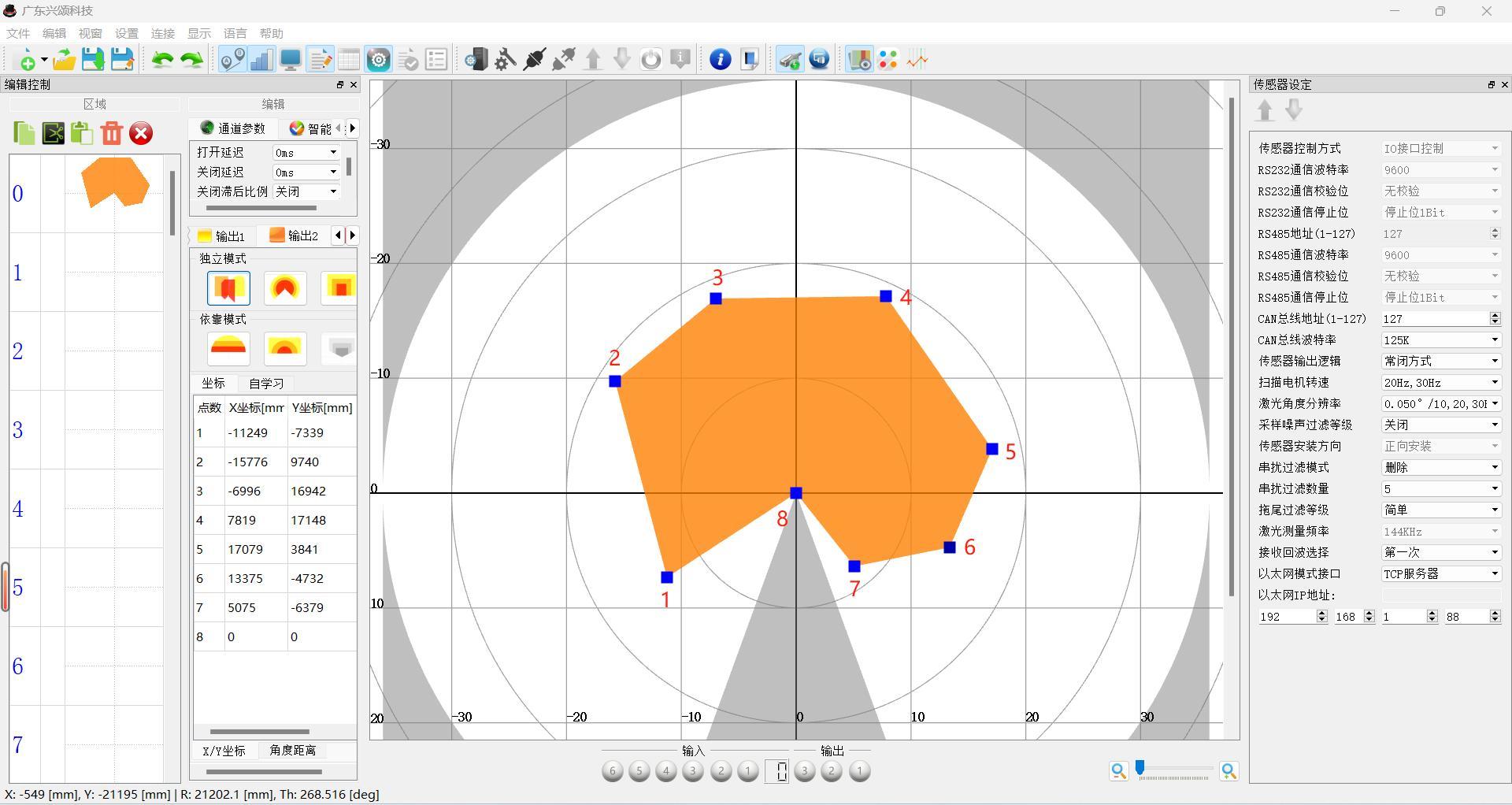
Note: Point 8 is the origin of the coordinates.
Distances and angles of each point of the irregular shape from the origin in independent mode:
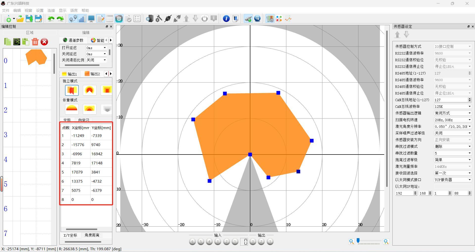
Note: Point 8 is the origin of the coordinates.
6.2.7 Scanning Status Display
Scanning profile, reflection intensity, detection channel graphic display area
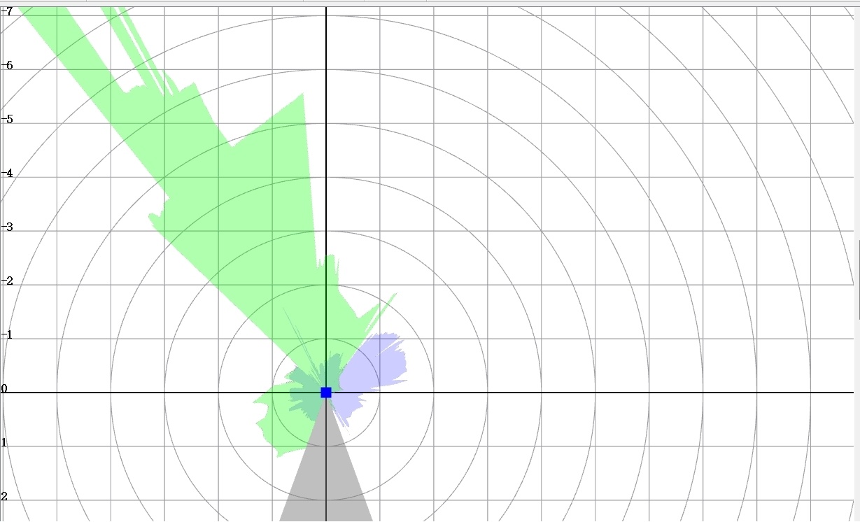
Note: 1 The green line indicates the scanning profile, 2 The blue line indicates the reflection intensity.
6.2.8 Input and Output Monitoring
- 4 switch quantity inputs and 2 switch quantity outputs
- 4 switch quantity inputs select detection channels 48-63 (can also specify the selected channel via Ethernet)
- 2 switch quantities output the status signals of output 1 and output 3 respectively.
Parameter List |
Parameter Value |
Remarks |
|---|---|---|
Sensor Control Method |
IO Interface Control |
When selecting the sensor channel, choose one from IO, Modbus, Canopen; only one can be effective at the same time, IO is always effective during output. |
Modbus Communication Control |
When selecting the sensor channel, choose one from IO, Modbus, Canopen; only one can be effective at the same time, IO is always effective during output. When Modbus communication control is selected, Modbus output is effective. |
|
Canopen Communication Control |
When selecting the sensor channel, choose one from IO, Modbus, Canopen; only one can be effective at the same time, IO is always effective during output. When Canopen communication control is selected, Canopen output is effective. |
|
RS485 Address (1-127) |
1-127 |
RS485 communication address 1-127 can be set. |
RS485 Communication Baud Rate |
9600bps |
Setting of RS485 communication baud rate |
19200bps |
||
38400bps |
||
57600bps |
||
115200bps |
||
RS485 Parity Bit |
No Parity |
Setting of RS485 Parity Code |
Odd Parity |
||
Even Parity |
||
RS485 Communication Stop Bit |
Stop Bit 1Bit |
Setting of RS485 Stop Bit |
Stop Bit 1.5Bit |
||
Stop Bit 2Bit |
||
CAN Bus Address (1-127) |
1-127 |
CAN communication address 1-127 can be set. |
CAN Bus Baud Rate |
125K |
CAN Bus Baud Rate |
250K |
||
500K |
||
1000K |
||
Sensor Output Logic |
Normally Open Mode |
Sensor output normally open, normally closed setting |
Normally Closed Mode |
||
Laser Angle Resolution |
0.025°/12.5HZ
0.050°/12.5, 25HZ
0.100°/12.5, 25, 50HZ
0.200°/50HZ
0.250°/12.5, 25HZ
0.500°/12.5, 25, 50HZ |
Default Resolution 0.250° |
Noise Filtering Level |
Off
Simple
Medium
Strict |
Noise filtering level setting, default is off |
Sensor Installation Direction |
Forward Installation |
Parameter currently not effective |
Crosstalk Filtering Mode |
Off
Fitting
Delete |
Default Delete.
Enable interference prevention for other sensors |
Crosstalk filtering quantity |
3-8 |
Default is 5, the number of filtering points; the more filtering points, the better the anti-interference effect, but there will be some distortion in the edge parts of the image. |
Trailing filter level |
Off
Simple
Medium
Strict |
Trailing filter level setting, default is simple |
Laser measurement frequency |
540KHz |
Sensor measurement frequency, this parameter cannot be modified at present |
Echo selection |
First time
Second time
Last time
Maximum energy |
First time: normal mode, no filtering function
Second time: select the second echo, with filtering function
Last time: select the last echo, with filtering function
Maximum energy: select the echo with maximum energy, with filtering function
Default is the first time |
Dirt filtering distance |
0-2000 |
Dirt filtering distance setting, default is 200 |
Dirt filtering intensity |
0-2000 |
Dirt filtering distance setting, default is 200 |
Ethernet mode interface |
TCP server | Default TCP server |
UDP mode |
||
Ethernet IP address |
Setting of sensor IP address |
6.2.10 Multi-echo settings (for FE35FB-XXXXX)

|
|
First time |
Normal mode, no filtering function |
Second time |
Select the second echo, with filtering function (echo function recommended option) |
Last time |
Select the last echo, with filtering function |
Maximum energy |
Receive echo with maximum energy |
Note: In the case of multiple lasers, using the multi-echo function and selecting to delete the crosstalk filtering mode will result in some point cloud disappearing in the image. Please do not use the above functions simultaneously. |
|
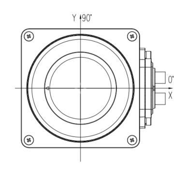
|
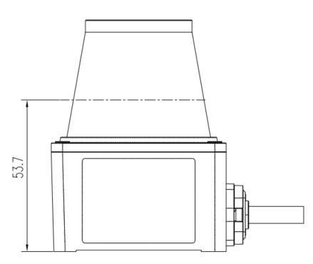
|
|
7.2.1 Filtering environment and minimum distance
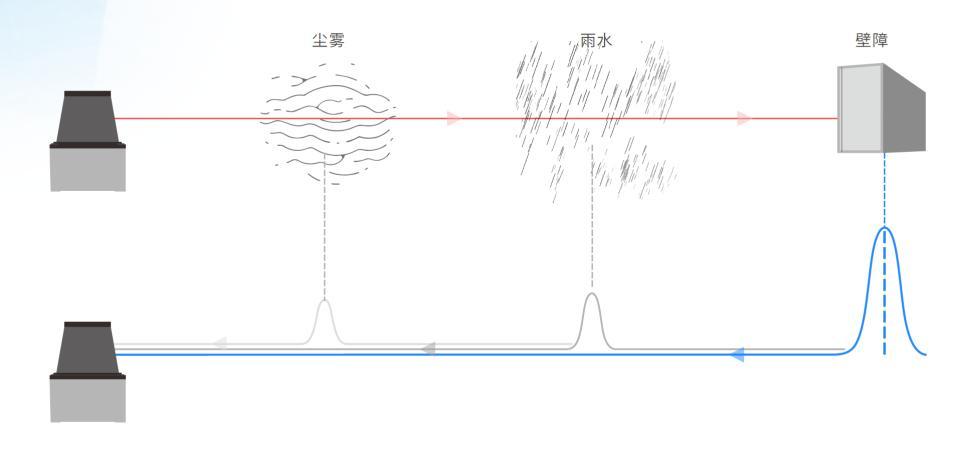
The multi-echo technology can detect multiple echo signals for each measurement beam, thus identifying echoes caused by rain, dust, or complex structures during the operation cycle of the emitted beam, and filtering them when necessary.
To display echoes as separate measurement values, there must be a minimum distance of about 2.5m between two objects.
7.2.2 The impact of object surfaces on measurements
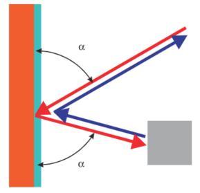
● Smooth reflective surfaces
Smooth reflective surfaces cannot be detected, but objects illuminated by the reflected light from smooth reflective surfaces can be detected.
● Detecting small objects or no objects
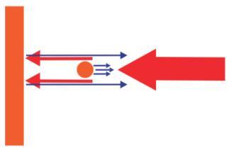
If the detected object is smaller than the beam diameter, it may be the case that
① The surface of the small object reflects insufficiently, and there are no background objects, so it cannot be detected;
② The small object reflects insufficiently, but the background object reflects sufficiently, leading to detection errors;
③ Both the small object and the background object reflect sufficiently, resulting in distorted measurement values;
7.3 Ethernet data transmission
◆ Parameter settings
Open the configuration software, enter the sensor (server side) setting interface, and set the following parameters.

|
Parameter name |
Parameter Value |
Default value |
Ethernet mode |
TCP server |
TCP server |
|
UDP mode |
|||
Ethernet IP address |
192.168.1.1-254
The last byte can be set from 1-254
The sensor (server) port is fixed at 8080 |
192.168.1.88 |
After the client initiates a request and establishes a connection, data transmission begins, following these rules:
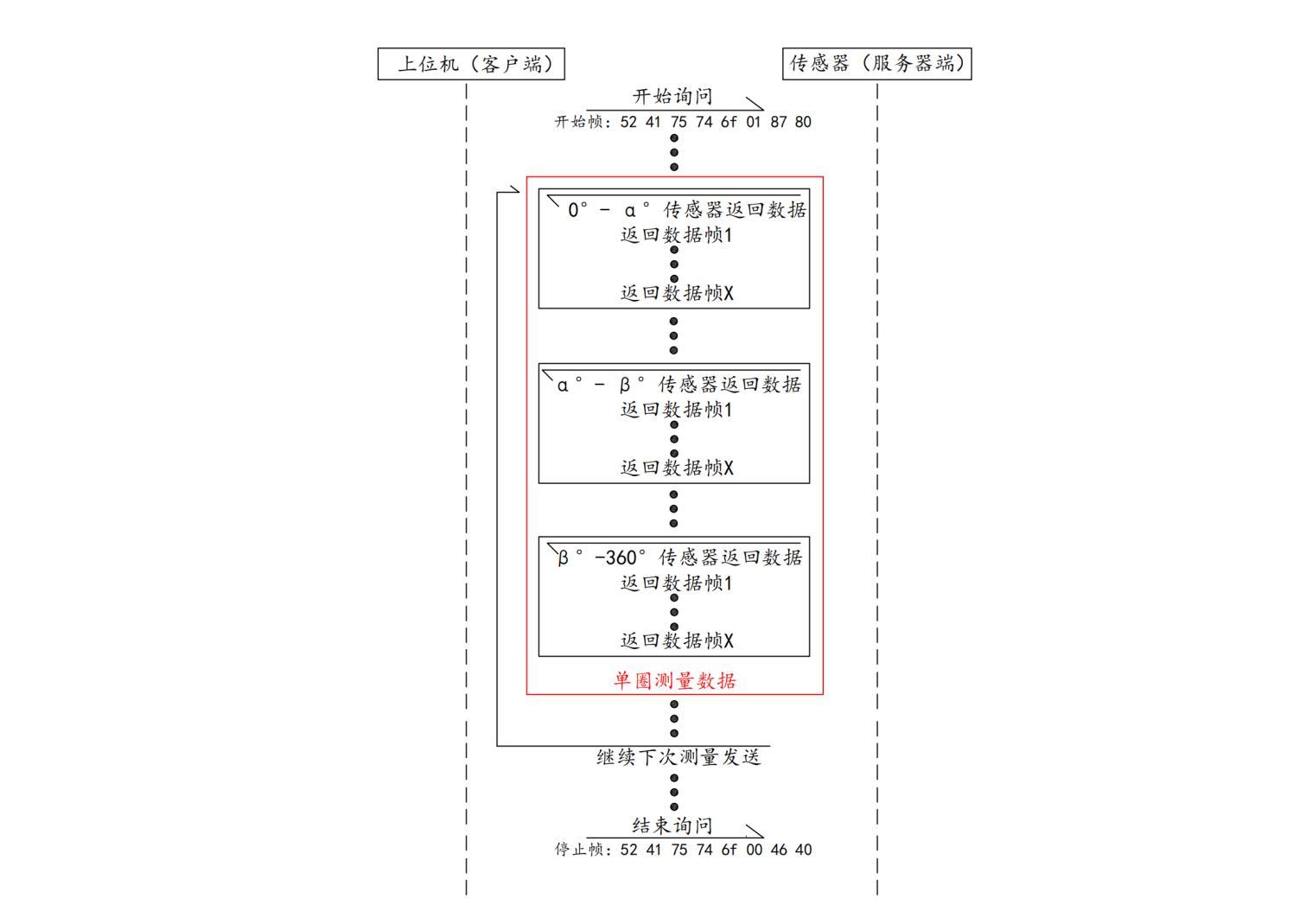
The host computer (client) sends a 'start data frame' to the sensor (server side), and the sensor returns measurement data for 0°-360° in several frames. After returning the complete measurement data for 0°-360° (a total of 360°), the sensor continues to send the next measurement data until it receives a 'stop data frame' sent by the host computer.
- Start data frame (Hex)
Data structure
Start code
|
Control bit
|
Check bit
|
5Byte
|
1Byte
|
2Byte
|
Start code:Fixed data is0x52 0x41 0x750x740x6F
Control bit:
0x01The sensor starts to automatically send data;
0x00The sensor stops sending data;
Check bit:Low byte first, high byte last, using Modbus-CRC16The check bit calculated by the method.
- Measurement data frame (Hex)
Data structure:
Data frame header
|
Measurement data
|
16Byte
|
Variable length
|
Data frame header format (Hex):
Identifier
|
1Byte
|
1Byte
|
|
1Byte
|
|
1Byte
|
|
Starting angle
|
1Byte (high byte first)
|
1Byte (low byte last)
|
|
Ending angle
|
1Byte (high byte first)
|
1Byte (low byte last)
|
|
Total number of measurement points in the current data frame
|
1Byte (high byte first)
|
1Byte (low byte last)
|
|
Sequence number of the last detection point in the current data frame
|
1Byte (high byte first)
|
1Byte (low byte last)
|
|
Total number of measurement points from the starting angle to the ending angle
|
1Byte (high byte first)
|
1Byte (low byte last)
|
|
Time stamp
|
1Byte (high byte first)
|
1Byte (low byte last)
|
1. Identifier (4Byte): 0x48 0x49 0x53 0x4e
2. Starting angle (2Byte): The starting angle of the current returned measurement data;
3. Ending angle (2Byte): The ending angle of the current returned measurement data;
4. Total number of measurement points in the current data frame (2Byte):
Due to different angle resolutions, the total number of measurement points in the range from the starting angle to the ending angle will also vary. The measurement data will be returned in several data frames within this range. The 'total number of measurement points in the current data frame' is the sum of the measurement points returned in the current data frame.
5. Sequence number of the last detection point in the current data frame (2Byte):
For example: The total number of measurement points from the starting angle to the ending angle is800, divided into 2 frames to return measurement data. The current data frame returns data for points 1 to400, then the value of 'sequence number of the last detection point in the current data frame' is400, if the current data frame returns from point401to800, then the value of 'sequence number of the last detection point in the current data frame' is800.
6. Total number of measurement points in the range from the starting angle to the ending angle (2Byte):
The total number of measurement points in the range from the starting angle to the ending angle is determined by the current 'laser scanning frequency', 'scanning motor speed', and 'single point sampling
times'. The following will provide examples.
7. Time stamp (2Byte):
Displays the internal timing of the current frame sent, time unit is us, time recording range is 0-65535us, data is cleared after recording is full.
Measurement data (Hex):
First point measurement data (4Byte)
|
Second point measurement data (4Byte)
|
………………… (4Byte)
|
Last point measurement data (4Byte)
|
||||||||||||
Measurement distance (2Byte)
|
Measurement intensity (2Byte)
|
Measurement distance (2Byte)
|
Measurement intensity (2Byte)
|
Measurement distance (2Byte)
|
Measurement intensity (2Byte)
|
Measurement distance (2Byte)
|
Measurement intensity (2Byte)
|
||||||||
L
|
H
|
L
|
H
|
L
|
H
|
L
|
H
|
L
|
H
|
L
|
H
|
L
|
H
|
L
|
H
|
The unit of measurement distance is mm, outputting the distance data between the reflection point and the sensor.
Measurement intensity reflects the intensity of the reflection point, with higher values indicating stronger reflection capability of the object.
Both measurement distance and measurement intensity are low byte first, high byte last.
- Stop data frame (Hex)
0x52 0x41 0x75 0x74 0x6F 0x00 0x46 0x40
After the host computer sends the stop data frame to the sensor, the sensor stops returning measurement data.
- Example explanation
1. The sensor parameters are set as follows:
Ethernet mode interface: TCP server
Ethernet IP address: 192.168.1.88
Scanning motor speed: 12.5HZ
Sensor (server) port: 8080
It is important to note that the sensor (server) port is fixed at 8080, and the host computer successfully establishes a connection with the sensor..
2. Calculation of measurement angle resolution:
Laser scanning frequency: The number of laser beams emitted by the laser emitter in one second, taking 432KHZ as an example;
Scanning motor speed: the number of revolutions of the laser emission tube rotating motor in one second, taking 12.5HZ (12.5r per second) as an example;
Single point sampling times: the number of repeated measurements at a single measurement point. Taking a single detection point measurement as an example;1times;
Measurement angle resolution = scanning motor speed * 360° / (laser scanning frequency / single point sampling times) =0.100°, the measurement angle resolution is automatically calculated by the configuration software and does not need to be set separately;
3. Calculation of total measurement points:
Total measurement points = (end angle - start angle) / measurement angle resolution, the total measurement points are rounded to one decimal place, and according to the design of the sensor, it is divided into 13 angular range data blocks. This angular range value is fixed and does not change with the change of angle resolution. See Figure 4 below.
First start angle
|
First end angle
|
Angle range
|
Second start angle
|
Second end angle
|
Angle range
|
Third start angle
|
Third end angle
|
Angle range
|
Fourth start angle
|
Fourth end angle
|
Angle range
|
24°
|
48°
|
24°
|
48°
|
72°
|
24°
|
72°
|
96°
|
24°
|
96°
|
120°
|
24°
|
Fifth start angle
|
Fifth end angle
|
Angle range
|
Sixth start angle
|
Sixth end angle
|
Angle range
|
Seventh start angle
|
Seventh end angle
|
Angle range
|
Eighth start angle
|
Eighth end angle
|
Angle range
|
120°
|
144°
|
24°
|
144°
|
168°
|
24°
|
168°
|
192°
|
24°
|
192°
|
216°
|
24°
|
Ninth start angle
|
Ninth end angle
|
Angle range
|
Tenth start angle
|
Tenth end angle
|
Angle range
|
Eleventh start angle
|
Eleventh end angle
|
Angle range
|
Twelfth start angle
|
Twelfth end angle
|
Angle range
|
216°
|
240°
|
24°
|
240°
|
264°
|
24°
|
264°
|
288°
|
24°
|
288°
|
312°
|
24°
|
Thirteenth start angle
|
Thirteenth end angle
|
Angle range
|
|
|
|
|
|
|
|
|
|
312°
|
336°
|
24°
|
|
|
|
|
|
|
|
|
|
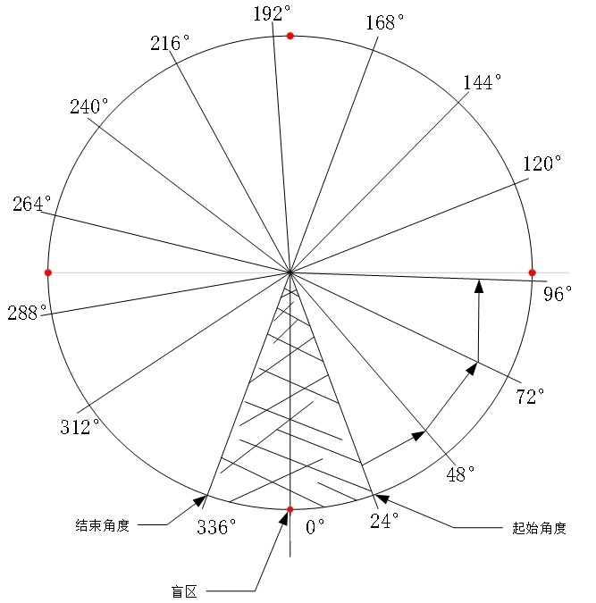
Taking the end angle of 24°, start angle of 0°, and angle resolution of 0.100° as an example, total measurement points = (24-0) / 0.100 = 240.
Sensor status and area detection data acquisition
After initiating a request and establishing a connection on the client side, data transmission begins, following the rules below.
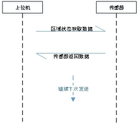
Data acquisition sendingMessage
Data identifier
|
5Byte
|
Sensor working mode
|
1Byte
|
Sensor channel value
|
1Byte
|
Switching angle value in intelligent channel selection mode
|
2Byte
|
Switching speed value in intelligent channel selection mode
|
2Byte
|
Channel group number
|
2Byte
|
Invalid data bit
|
3Byte
|
Check bit
|
2Byte
|
- Data identifier (5byte)
Identifier is fixedData:0x57 0x53 0x69 0x6d 0x75The function of this data;
- Sensor working mode (1byte)
00: Invalid command
01: Channel designated mode
02: Intelligent channel selection mode
- Sensor channel value (1byte)
Control the current sensing channel used by the sensor, data range 00-63;
- Sensor channel angle (2byte)
Angle value in channel group mode, data is in the signed data range -180 to 180;
- Sensor channel speed value (2byte)
Speed value in channel group mode, data is in the signed data range -300-300;
- Sensor channel group number (2byte)
Control the current sensing channel group number used by the sensor, data range 00-04;
- Invalid data (3byte)
Invalid data, default data must be sent0x00;
- Check bit (2byte)
Data check bit, using modbus low byte first CRC16Check method. The check value is calculated using the check formula, for specific calculation methods see the appendix.
Sensor return data
Data identifier
|
5Byte
|
Sensor channel value
|
1Byte
|
Invalid
|
1Byte
|
Output status
|
1Byte
|
Invalid data
|
1Byte
|
Fault status
|
1Byte (H)
|
|
1Byte (L)
|
Current temperature
|
1Byte
|
|
1Byte
|
Internal motor speed
|
1Byte (H)
|
|
1Byte (L)
|
Drive voltage
|
1Byte (H)
|
|
1Byte (L)
|
Receiving voltage
|
1Byte (H)
|
|
1Byte (L)
|
Sending voltage
|
1Byte (H)
|
|
1Byte (L)
|
Check bit
|
1Byte (L)
|
|
1Byte (H)
|
- Data identifier (5byte)
Identifier is fixedData:0x57 0x53 0x69 0x6d 0x75The function of this data;
- Current channel value (1byte)
Current channel value of the sensor;
- Invalid data (1byte)
Invalid data;
- Output status (1byte)
Bit7
|
Bit6
|
Bit5
|
Bit4
|
Bit3
|
Bit2
|
Bit1
|
Bit0
|
Invalid
|
OUT 3
|
OUT2
|
OUT1
|
||||
Related to parameter settingsSensor Output Logic:
Normally closed mode (default)
00: Object detected;
01: Object not detected
Normally Open Mode
01: Object detected;
00: Object not detected;
- Invalid data (1byte)
Invalid data;
- Sensor fault status (2byte)
|
||||||||||||||||||||||||||
Sensor fault code
|
- Current temperature (2byte)
|
||||
Signed data, data range -5000-10000; displays the current internal temperature of the sensor, temperature unit 0.01℃; when the monitored temperature exceeds 80.00℃, the sensor indicates over-temperature protection;
|
||||
- Internal motor speed (2byte)
|
||||
Unsigned data, data range 0-3000, displays the current internal motor speed of the sensor, speed unit 1r/min;
|
||||
- Drive voltage (2byte)
|
||||
Unsigned data, data range 0-1600; displays the current sensor drive motor voltage, voltage unit 0.01V;
|
||||
- Receiving board voltage (2byte)
|
||||
Unsigned data, data range 0-25000; displays the current sensor receiving board ADP voltage, voltage unit 0.01V;
|
||||
- Sending board voltage (2byte)
|
||||
Unsigned data, data range 0-5500; displays the current sensor sending board voltage, voltage unit 0.01V;
|
||||
- Check bit (2byte)
Data check bit, using modbus low byte first CRC16Check method. The check value is calculated using the check formula.
cBuffer: Array for calculating CRC check code.
iBufLen: Length of the array.
unsigned int CRC_Verify(unsigned char *cBuffer, unsigned int iBufLen)
{
unsigned int i, j; //#define wPolynom 0xA001
unsigned int wCrc = 0xffff;
unsigned int wPolynom = 0xA001;
/*---------------------------------------------------------------------------------*/
for (i = 0; i < iBufLen; i++)
{
wCrc ^= cBuffer[i];
for (j = 0; j < 8; j++)
{
if (wCrc &0x0001)
{ wCrc = (wCrc >> 1) ^ wPolynom; }
else
{ wCrc = wCrc >> 1; }
}
}
return wCrc;
}
For customers using sensors in a ROS environment, specific provided drivers can be used. The ROS driver package can be obtained as follows:
Visit: www.hinson-xs.com
|
Contact Hinson sales and technical support personnel
|
Visit Gitee:https://gitee.com/hinson-xs/hins_he_driver.git
|
When the sensor fails to operate normally or the sensor status cannot be determined, refer to the following table for fault diagnosis and confirmation.
The laser sensor indicates fault status through LED flashing:
LED Flashing (Times)
|
Fault Description
|
0
|
Sensor normal status
|
1
|
Sensor encoder signal error
|
2
|
No receiving board signal
|
3
|
Memory data error
|
4
|
Connection error
|
5
|
Simulation error
|
6
|
Over-temperature protection
|
7
|
Sending under-voltage protection
|
8
|
Sending over-voltage protection
|
9
|
Drive under-voltage protection
|
10
|
Drive over-voltage protection
|
11
|
Receiving under-voltage protection
|
12
|
Receiving over-voltage protection
|
9.1 Warranty Period
* The sensor provides a limited warranty. During the warranty period, if the product cannot be used normally due to quality issues or design defects, we will provide free after-sales maintenance.
* Warranty period: 2 years from the date of sale.
* Products within the warranty period that meet warranty conditions will be repaired or replaced free of charge.
* This product's warranty and after-sales service are limited to mainland China;
* Products that cannot be used normally due to damage during transportation;
* Products that cannot operate normally due to damage to components themselves;
* Products that cannot be used normally due to design defects;
9.3 Exemption Scope
* Please pay attention to the following conditions during product use; we will not provide free after-sales service and warranty.
* Damage caused by incorrect installation of the product according to the manual;
* Damage caused by using the product in unsuitable environments and conditions;
* Damage caused by not following the product manual specifications;
* Unauthorized disassembly or repair of the product without the company's permission;
* Damage caused by natural disasters, fires, and other irresistible external forces.
9.4 Technical Support
If there are unresolvable faults, please contact us as follows.
Phone: +86-757-22218956
Email: lixianjiao@hinson-xs.com
Company Website:www.hinson-xs.com
Manufacturer: Guangdong Hinson Technology Co., Ltd.
Table of Contents
1.1. Applicable Environment Precautions
1.2. Wiring Environment Precautions
1.3. Debugging Environment Precautions
4.3. Indicator Light Description
4.4. Installation Requirements
5.1. Power and Switch Quantity Ports
5.2. Input and Output Signal Connections
5.2.1. Input Signal Connection
6.2. Connection between Sensor and Configuration Software
6.2.1. Open Configuration Software
6.2.4. Detection Channel Graphic Editing
6.2.6. Coordinates and Their Angle Values
6.2.7. Scanning Status Display
6.2.8. Input and Output Monitoring
6.2.10. Multi-echo Settings (for FE-XXXXXFA only)
7.2.1. Filtering Environment and Minimum Distance
7.2.2. The impact of object surface on measurement
7.3. Ethernet data transmission
Solutions for your industry, ready for your choices

Hinson
Guangdong Hinson Technology Co., Ltd.
Support customers to become industry leaders
Industrial automation sensing and control solution provider

WeChat Public Number
Business consulting
Service Hotline
Building 8, Shengyue Garden, 33 Shunye East Road, Xingtan Town, Shunde District, Foshan City, Guangdong Province
(Shunde Machinery Industrial Park)


